
Flanged Puddle Flange Connection
A welded flange provides a bolted joint for valves, pumps, tanks or removable pipe sections. Buyers should specify its standard, rating, facing and orientation.
Mesta Inc. manufactures puddle flange connection assemblies with drawing-defined pipe ends, flange standards, plate geometry, materials and finishes. Therefore, each unit can connect correctly to the adjoining pipeline while forming a reliable water stop within concrete.
A puddle flange connection joins an embedded water-stop pipe assembly to the adjoining pipeline or equipment. The central puddle plate remains cast into concrete, while one or both accessible pipe ends receive the specified connection. As a result, the assembly supports both penetration waterproofing and practical pipework installation.
The connection may use a welded flange, plain end, bevelled end, threaded end, socket or spigot. However, the term “puddle flange” describes the embedded water-stop feature rather than one universal end joint. Designers must therefore specify the end arrangement independently.
Mesta Inc. manufactures each pipe puddle flange from an approved drawing. We coordinate the pipe outside diameter, puddle plate position, overall length, end preparation and flange orientation so installers receive a complete, compatible assembly.
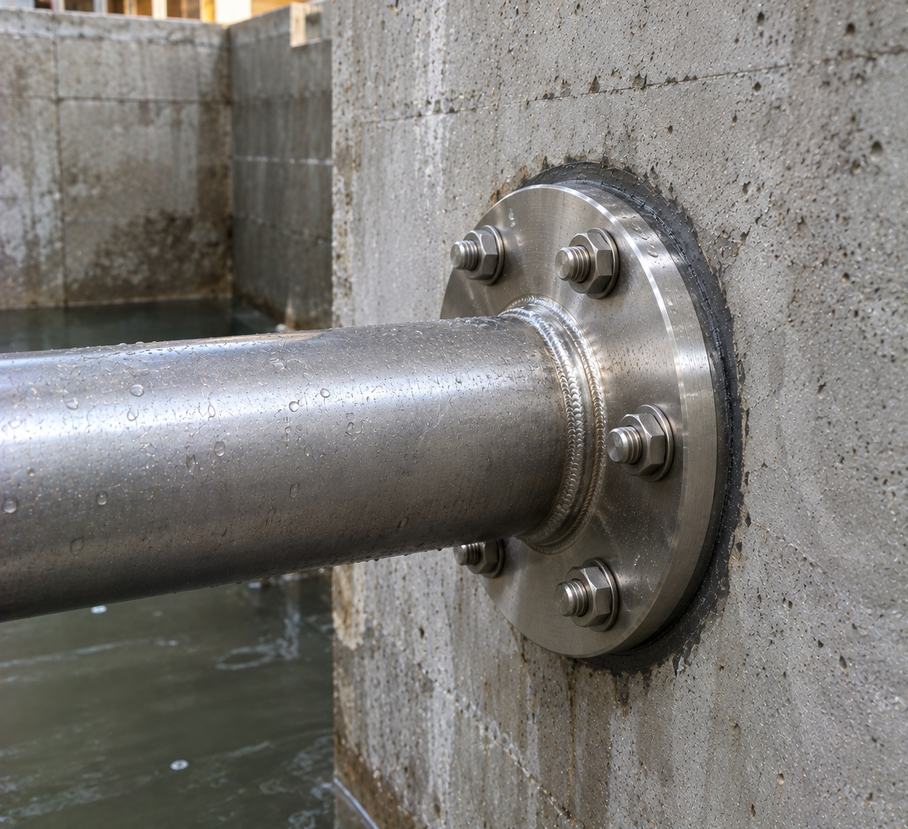
A nominal pipe size alone cannot define a complete connection. Accordingly, the purchase specification should identify every interface that affects fabrication and site installation.
| Pipe details | Nominal size, actual outside diameter, wall thickness, schedule and material grade. |
|---|---|
| Connection type | Flanged, plain, bevelled, threaded, socket, spigot or another approved end arrangement. |
| Flange standard | Applicable dimensional standard, nominal size, pressure class or PN rating and material. |
| Facing and drilling | Raised face, flat face or other facing, plus bolt-hole number, diameter and orientation. |
| Puddle plate | Outside diameter or width, thickness, profile, opening and location along the pipe. |
| Assembly length | Overall length and required projection on each side of the concrete structure. |
| Joint components | Gasket, bolts, nuts, washers, coupling or site-weld details when included in the scope. |
| Surface protection | Coating, galvanizing, pickling, passivation or another service-compatible finish. |
| Testing | Material review, dimensional inspection, weld examination and pressure or leak testing when specified. |
Compatibility note: Never select a mating flange by nominal size alone. Confirm the standard, class, facing, drilling, gasket and material before fabrication.
The correct end arrangement depends on the connected system, access and maintenance plan. For example, a removable equipment connection may need a flange, whereas a permanent line may use a welded joint.
A welded flange provides a bolted joint for valves, pumps, tanks or removable pipe sections. Buyers should specify its standard, rating, facing and orientation.
A plain end can suit a coupling, while a bevelled end supports a field butt weld made under an approved procedure.
One end carries a flange and the other provides a spigot or plain connection. This arrangement helps join different pipeline interfaces across a wall or slab.
Flanges at both ends create accessible bolted connections on each side of the concrete penetration. Overall length and bolt-hole alignment require careful control.
Compare our single flanged pipe, double flanged pipe and flange spigot pipe with puddle options.
First, identify the connected pipework and operating conditions. Then, match the connection interface to the project drawings and specifications.
For general flange terminology and standards development, buyers may also consult the ASME Codes & Standards resources.
Design note: A puddle plate limits water tracking through concrete. However, it does not replace the gasket, weld, coupling seal or other joint element needed to seal the pipe connection itself.
Correct installation protects the embedded assembly and helps the external joint align without forced fit-up.
First, confirm the assembly tag, pipe size, flange standard, end type, orientation and concrete location.
Next, check dimensions, sealing faces, welds, coating and protective covers before positioning.
Use independent supports to hold the assembly at the required level, alignment and embedment depth.
Keep flange faces, threads, sockets and weld preparations free from concrete, dirt and damage.
Then, compact concrete around the plate without disturbing the pipe position or leaving voids.
Finally, connect the pipeline with the specified gasket, bolts, weld or coupling and inspect the completed joint.
Inspection should cover both the embedded water-stop assembly and its accessible connection ends. Therefore, a typical plan checks the following items.
Inspectors verify the pipe OD, wall thickness, plate geometry, assembly length and plate position.
The team confirms the standard, class, facing, drilling, thickness and bolt-hole orientation.
Required weld examination, coating checks, passivation records and visual inspection follow the agreed scope.
After installation, technicians check alignment, gasket seating, bolt tightening or field-weld acceptance as applicable.
These assemblies connect pipework across concrete walls, slabs and tank structures where water may track along the penetration. Common applications include:
Projects may also require a concrete slab puddle flange, stainless steel puddle flange or adjustable puddle flange.
Send complete interface data so the quotation and fabrication drawing match the adjoining pipework.
It is the end interface that joins an embedded puddle flange pipe assembly to adjoining pipework or equipment. The assembly may use flanged, welded, plain, threaded, socket or spigot ends.
No. A puddle flange describes the water-stop plate embedded in concrete. Its pipe ends can use several connection methods, depending on the approved design.
Specify the dimensional standard, nominal size, pressure class or PN rating, facing, drilling, material and bolt-hole orientation. In addition, identify the gasket and fasteners.
Yes. For example, one side may have a bolted flange while the other uses a plain spigot, coupling or field-welded end.
No. The plate interrupts seepage along the pipe-to-concrete interface. The flange gasket, weld or coupling seal must provide joint tightness in the pipeline.
The fabrication drawing should show the bolt-hole orientation, flange-face position and required pipe projection. This information helps avoid forced alignment at site.
Provide the pipe and plate dimensions, end connections, flange standard, material, design conditions, overall length, inspection scope and quantity.
Send Mesta Inc. your drawings, pipe dimensions, end-connection details, materials, quantity and inspection requirements. Then, our team will review the interface and confirm the appropriate manufacturing scope.