
Straight Double Flanged Pipe
A straight barrel joins two aligned flanged components. Moreover, the drawing controls its exact face-to-face length.
Mesta Inc. manufactures double flanged pipe sections with controlled face-to-face dimensions, flange alignment and bolt-hole orientation. Moreover, buyers can add a central puddle plate for concrete wall or tank penetrations.
A double flanged pipe is a straight or drawing-defined pipe section with a bolted flange at each end. Consequently, installers can connect the piece between valves, equipment, pipelines or other flanged components without field welding at its ends.
The assembly may also include a central puddle plate when it passes through a concrete wall or tank. In that configuration, the plate acts as the embedded water stop, while the two end flanges provide separate bolted connections.
Mesta Inc. manufactures each double flange pipe to the approved drawing. Therefore, buyers should define the pipe size, face-to-face length, material, wall thickness, flange standard, pressure class, facing and bolt-hole orientation.
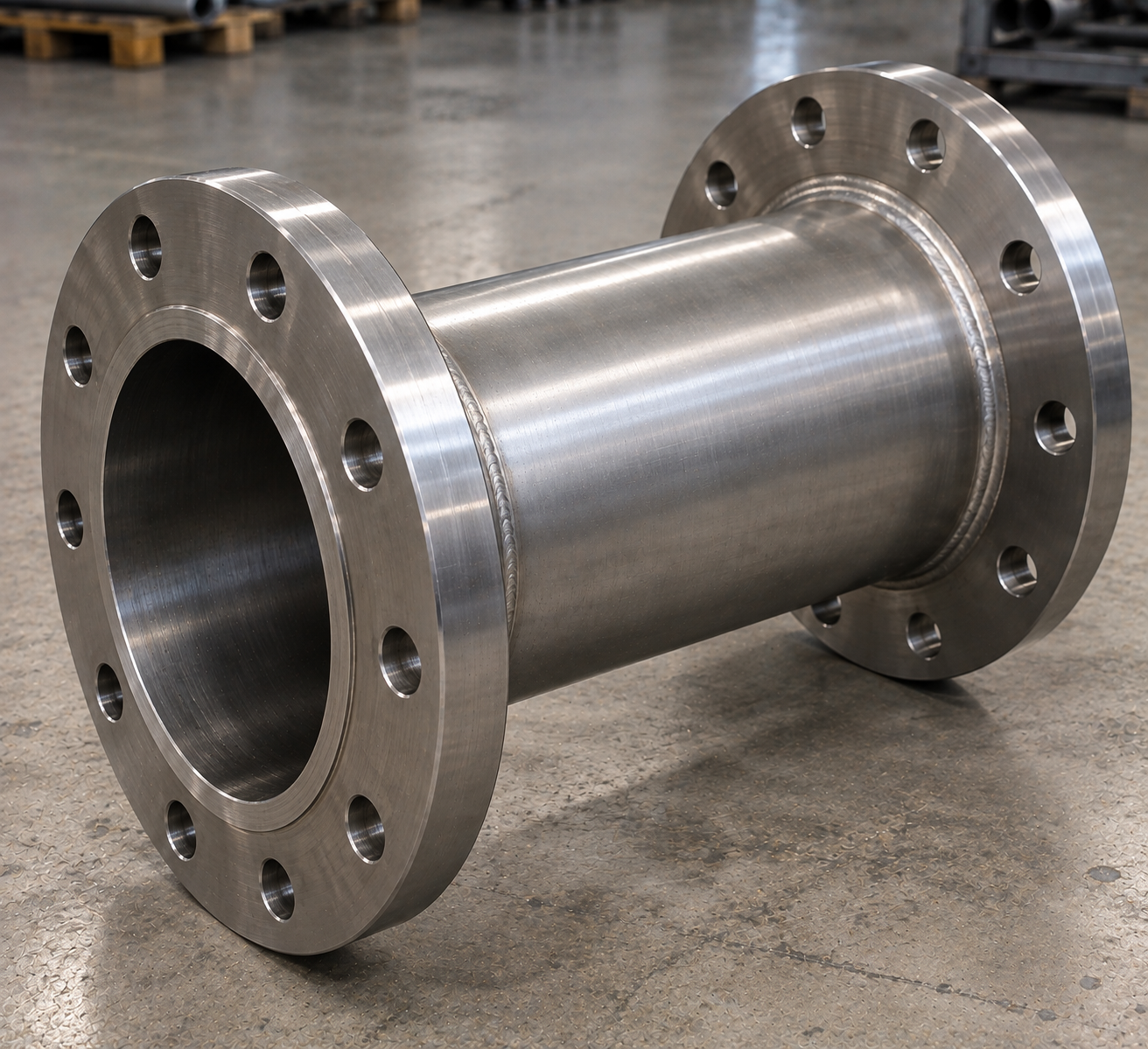
The term “double flanged pipe” defines the general configuration but not the finished dimensions or rating. Therefore, the purchase specification should include every item below.
| Nominal pipe size | Project-defined size together with the governing pipe and flange dimensional standards. |
|---|---|
| Pipe material | Carbon steel, stainless steel, alloy steel or another approved material and grade. |
| Pipe wall | Schedule or project-defined wall thickness according to size, material and service. |
| Face-to-face length | Distance between the two finished flange faces, with stated tolerance. |
| Flange standard | Project-specified dimensional standard for each end flange. |
| Pressure designation | Required class or pressure rating for the flanged connection system. |
| Flange facing | Flat face, raised face, ring-type joint or another specified facing as applicable. |
| Bolt-hole orientation | Straddle centreline or drawing-defined clocking for both flanges. |
| Optional puddle plate | Plate OD or width, thickness, position and material for wall-penetration assemblies. |
| Inspection and testing | Visual, dimensional, NDT, pressure testing, coating inspection and documentation as specified. |
Length note: State whether the required length is face-to-face, overall, flange-to-centreline or another drawing dimension. Otherwise, different interpretations can produce an unusable pipe piece.
The piping layout and installation method determine the flange and pipe arrangement. Consequently, buyers can define one of several configurations.
A straight barrel joins two aligned flanged components. Moreover, the drawing controls its exact face-to-face length.
An extended pipe section crosses a wall or chamber while its end flanges remain accessible on both sides.
A central puddle plate creates the embedded water stop for an RCC wall, slab or tank penetration.
A drawing may add a reducer, elbow or branch between the flanged ends when the piping design requires it.
Compare our single flanged pipe, flange-spigot pipe with puddle and puddle flange pipe pages.
Two flanges do not have to be identical, although many assemblies use matching ends. Therefore, specify each end independently:
Rating note: The flange class applies to the connection system, not automatically to every part of a wall-penetration assembly. The piping designer must confirm the complete pressure design.
A controlled fabrication sequence connects material traceability with face-to-face and flange-orientation accuracy.
First, confirm pipe data, face-to-face length, both flange details and any puddle plate.
Next, match the pipe, flanges and plate with the approved bill of materials.
Then, cut the pipe and prepare the flange weld ends according to the fabrication documents.
Fabricators establish face-to-face length, flange parallelism and bolt-hole orientation before welding.
Afterwards, qualified personnel complete welding and the specified visual or non-destructive examinations.
Finally, inspectors complete dimensional checks, testing, finishing, marking and documentation.
The inspection plan should address both pressure-boundary quality and installation dimensions. Accordingly, typical checks include:
First, markings and certificates connect the pipe, both flanges and optional plate to the BOM.
Inspectors check face parallelism, concentricity, facing condition and bolt-hole orientation.
The team performs visual and specified PT, MT, RT, UT or other examination as applicable.
Finally, inspectors complete specified pressure testing and surface-finish verification.
Projects use double flanged pipe sections where installers need removable bolted connections at both ends. For example, common applications include:
Additionally, wall-penetration projects can review concrete-wall puddle flanges, water-tank penetrations and CS water tank puddle flanges.
For accurate fabrication and pricing, send the approved drawing and these details:
It is a pipe section with a bolted flange at each end. Consequently, installers can connect it between compatible flanged components without field-welding its ends.
Yes, when the approved design requires dissimilar ends. However, the purchaser must specify each flange standard, class, facing and material separately.
It is the finished distance between the two flange faces. Therefore, buyers should state the required length and tolerance clearly.
Yes. A central puddle plate can create a water stop where the pipe passes through concrete, while the two end flanges provide bolted connections.
Correct orientation allows both flanges to align with fixed mating connections. Otherwise, installers may face misalignment at site.
Depending on the project, options can include carbon steel, stainless steel, alloy steel or other approved materials.
First, send the drawing, pipe material and face-to-face length. Then, provide full details for both flanges, welding, testing, coating and quantity.
Send Mesta Inc. your pipe dimensions, puddle plate details, material, drawing, quantity, inspection scope and delivery requirements. Then, our team will review the enquiry and confirm the appropriate manufacturing scope.