
Horizontal Pipe Through RCC Wall
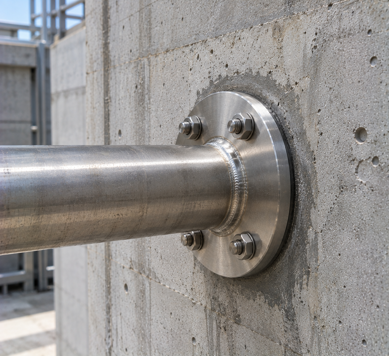
A straight pipe crosses the wall while the central plate provides the embedded water-stop projection.
Mesta Inc. manufactures concrete wall puddle flange assemblies to approved structural and piping drawings. Moreover, we coordinate the pipe size, water-stop plate, wall thickness, embedment, material, connection ends and inspection requirements.
Puddle Flange in Concrete Wall applications use a pipe or sleeve with a projecting water-stop plate embedded within the RCC wall. The plate interrupts the direct seepage path along the pipe surface. Therefore, it helps control leakage where services cross basements, tanks, pits and water-retaining structures.
The embedded plate addresses the pipe-to-concrete interface. However, it does not replace a pipe-joint seal, surface membrane, construction-joint waterbar or structural crack-control system.
Mesta Inc. manufactures each pipe puddle flange from a reviewed drawing. Buyers define the pipe OD, wall thickness, plate geometry, internal and external projections and connection ends.
A nominal pipe size cannot define the complete assembly. Accordingly, the drawing should state every penetration and connection requirement.
| Pipe size | Nominal size plus actual outside diameter, wall thickness or schedule. |
|---|---|
| Pipe material | Carbon steel, stainless steel, PVC, uPVC, HDPE or another approved material. |
| Wall thickness | Structural concrete depth at the penetration, including local thickening. |
| Puddle plate | Overall OD or width, thickness, radial projection, profile and opening. |
| Plate position | Drawing-defined location through the wall and relation to both concrete faces. |
| Pipe projections | Required accessible length inside and outside for connections and maintenance. |
| Connection ends | Plain, bevelled, socket, spigot, threaded or flanged ends. |
| Surface protection | Coating, galvanizing, pickling, passivation or compatible plastic finish. |
| Inspection | Material, dimensions, attachment, position, finish and agreed tests. |
Embedment note: Do not centre the plate automatically. Follow the approved structural and waterproofing detail, which should consider cover, reinforcement and the direction of water exposure.
Service direction and access determine the connection arrangement. Consequently, projects may use several drawing-defined forms.
A straight pipe crosses the wall while the central plate provides the embedded water-stop projection.
One or two flanges provide bolted connections for valves, equipment or removable pipeline sections.
An embedded sleeve creates a formed opening for a separate carrier pipe and approved annular sealing system.
A pipe enters or leaves a water-retaining wall at the specified elevation and connects to internal or external pipework.
For vertical penetrations, review the concrete slab puddle flange. For end interfaces, see our puddle flange connection guidance.
First, confirm the service route and water exposure. Next, coordinate the assembly with the structural, piping and waterproofing drawings.
Project teams may consult the American Concrete Institute for concrete design and construction resources. Nevertheless, the approved project specification must govern the penetration.
Design note: A puddle plate controls seepage beside the pipe inside concrete. Other joints, cracks and wall surfaces still require their specified waterproofing systems.
Accurate pre-pour positioning preserves the specified line, level and embedment.
First, verify the grid, elevation, orientation, wall thickness and drawing revision.
Next, check the pipe, plate, ends, attachment, finish and identification.
Confirm clearance from bars, waterbars, form ties and other embedded items.
Use independent supports to hold the assembly level and prevent movement during the pour.
Then, compact concrete beneath and around the complete plate without leaving voids.
Finally, check alignment and finish before completing the adjoining pipe joints.
Inspection should cover fabrication and site position. Accordingly, typical checks include:
Inspectors verify certificates, pipe OD, plate geometry, assembly length and ends.
The team examines welds or bonded joints, coatings and protected surfaces.
Site checks confirm elevation, level, embedment and reinforcement clearance.
Inspectors review exposed ends, alignment, damage and visible concrete defects.
Concrete wall water stops support pipe entries in many below-grade and water-retaining structures, including:
Material-specific choices include a stainless steel puddle flange and PE puddle flange.
Provide complete penetration data so the quotation matches the installation.
Its projecting plate interrupts water tracking along the outside of a pipe embedded through the wall.
Not automatically. The approved structural and waterproofing drawing should define its position.
Yes. Specify the flange standard, rating, facing, drilling and bolt-hole orientation.
No. The puddle plate manages the embedded pipe interface, while the membrane protects the wall surface.
Yes, when the drawing defines a sleeve and a compatible annular seal for the carrier pipe.
Options may include steel, stainless steel, PVC, uPVC, HDPE or another approved material.
Send the pipe, plate and wall dimensions, material, ends, finish, inspection scope, quantity and drawings.
Send Mesta Inc. your penetration drawing, pipe dimensions, wall depth, plate details, materials, connection ends, quantity and inspection scope. Then, our team will review the enquiry.