
Factory-Welded Puddle Pipe
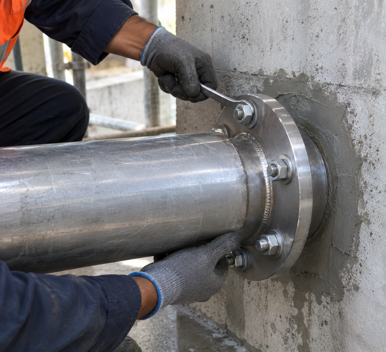
The plate arrives attached to a pipe spool. Installers position and support the complete assembly before casting.
Installing a puddle flange correctly requires an approved penetration detail, accurate positioning, rigid pipe support and careful concrete placement. Therefore, check the product drawing and project specification before work begins.
Installing a puddle flange starts with understanding how the water-stop component works inside a concrete wall or slab. Its projecting plate or collar interrupts the direct seepage path along the pipe-to-concrete interface. However, the component works as one part of the complete penetration design rather than as a substitute for sound concrete or required joint waterproofing.
Most installations take place before workers cast the concrete. The team fixes the pipe at the correct line and level, locates the plate within the wall, protects the exposed ends and then consolidates concrete around the full projection.
The approved project detail always takes priority over a general guide. In addition, qualified personnel should control lifting, welding, formwork and concrete operations under the site method statement. Consult applicable local requirements and an official workplace-safety resource such as OSHA where relevant.
Before installing a puddle flange, complete the required dimensional and coordination checks. Consequently, the team can correct problems before the component becomes embedded.
| Approved documents | Confirm the latest drawing, method statement, inspection plan and manufacturer instructions. |
|---|---|
| Pipe dimensions | Check nominal size, actual OD, wall thickness, material and end connections. |
| Plate geometry | Verify outside diameter or width, thickness, pipe opening and attachment detail. |
| Embedment position | Confirm wall thickness, plate centreline or offset, pipe elevation and orientation. |
| Reinforcement clearance | Coordinate the plate and pipe with reinforcement, concrete cover and nearby cast-in items. |
| Product condition | Inspect welds, coating, surfaces, flange faces, sockets, spigots and identification. |
| Supports and formwork | Plan stable supports and sealed formwork openings without loading the pipe incorrectly. |
| Concrete access | Provide enough space for placement and consolidation around the full water-stop projection. |
The correct procedure for installing a puddle flange depends on how the water stop connects to the pipe. Consequently, identify the component type before planning the work.
The plate arrives attached to a pipe spool. Installers position and support the complete assembly before casting.
The collar fits over a compatible metal pipe and requires an approved weld procedure, location and inspection.
The system uses manufacturer-defined seals, segments or fasteners and needs the specified tightening sequence.
The attachment method must suit the exact pipe material; do not apply a metal welding procedure to plastic.
Important: do not improvise welding, adhesives, sealants or clamp torque. Follow the approved design and the instructions for the exact pipe and flange system.
The sequence below describes a typical pre-pour installation. Nevertheless, the project procedure controls the actual work.
First, transfer the approved coordinates and mark the wall faces, pipe centreline and required projections.
Next, verify dimensions, item identification, material, coating and connection-end condition.
Then, install the welded, clamped or manufacturer-designed flange by its approved procedure.
Set the pipe accurately and use independent supports that resist movement during the concrete pour.
Close gaps around the pipe without changing alignment, damaging coatings or blocking concrete access.
Finally, record position, projection, support, cleanliness, reinforcement clearance and released hold points.
When installing a puddle flange, concrete quality around the plate remains central to the penetration detail. Therefore, coordinate the pour with the site concrete team.
Void risk: a horizontal plate surface can trap air or obstruct concrete flow. The formwork, reinforcement and placement sequence must allow full consolidation around both sides of the projection.
Document the installation before concrete hides the assembly. Accordingly, the inspection record may include:
Confirm pipe centreline, elevation, orientation, wall position and projection on each side.
Measure the water-stop location, radial projection, reinforcement clearance and concrete cover.
Check specified welds, clamps, seals or fasteners against the released installation procedure.
Review cleanliness, coating condition and protection of flange faces, threads, sockets or spigots.
Verify bracing, stability and sealed openings while preserving space for concrete placement.
Capture photographs, measurements, inspection results and approval before closing the hold point.
Small coordination errors can become difficult to correct after casting. Thus, avoid these common problems:
| Wrong pipe OD | Nominal size was used without checking the actual outside diameter and pipe standard. |
|---|---|
| Incorrect plate location | The flange was set at the wrong wall offset or conflicted with reinforcement. |
| Weak temporary support | The pipe moved under reinforcement loads, wet-concrete pressure or vibration. |
| Blocked concrete flow | Congested steel or a large plate prevented proper placement under the projection. |
| Unapproved attachment | Workers used site welding, sealant or clamps without an approved method. |
| Damaged connection ends | Concrete slurry or handling damaged flange faces, threads, sockets or spigots. |
| Dissimilar-metal contact | The installation omitted specified isolation between incompatible materials. |
| No pre-pour record | Critical dimensions and attachment details were not documented before concealment. |
After installing a puddle flange and completing the pour, wait until the concrete reaches the required condition. Then, once the project authorizes formwork removal, inspect the exposed assembly.
The approved structural and waterproofing detail defines the position. Designers often coordinate it within the wall thickness while maintaining reinforcement clearance and concrete cover.
Most cast-in systems are positioned before the pour. However, adjustable or proprietary retrofit systems may use a different method, so follow their approved instructions.
Only when the design permits site welding and an approved procedure covers the pipe material, flange material, joint, inspection and safety controls.
Use independent, engineered temporary supports or bracing. Check line and level again before concrete placement and monitor the assembly during the pour.
No single component guarantees performance. The result also depends on flange geometry, attachment, concrete quality, compaction, joints, movement and the complete waterproofing design.
Yes, when the design calls for direct embedment and surfaces meet the specification. Workers must place and consolidate concrete around the complete plate without leaving voids.
Check the product, pipe location, plate position, attachment, reinforcement clearance, supports, formwork, cleanliness and protected connection ends.
Send Mesta Inc. the approved penetration drawing, pipe dimensions, wall thickness, plate geometry, material and quantity. Then, our team can review the manufacturing requirements.