
Single-Flanged Wall Pipe
One bolted end connects to pipework, while the opposite end remains plain, bevelled or otherwise prepared.
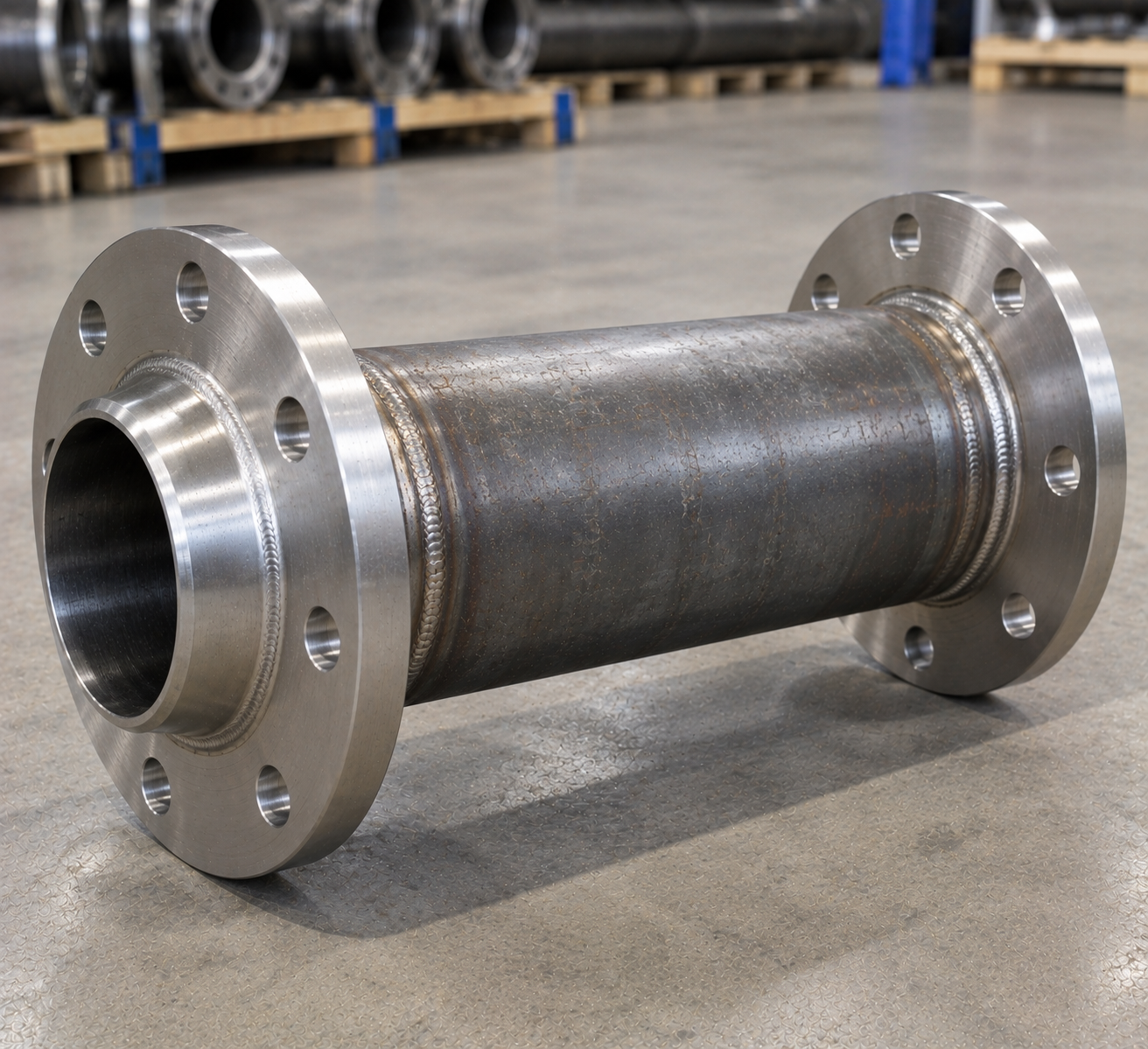
A pipe puddle flanged assembly combines a pipe spool, an integral water-stop plate and one or more bolted connection flanges. Moreover, Mesta Inc. controls the pipe material, plate position, flange standard, pressure class, facing, drilling and orientation.
The term pipe puddle flanged describes a penetration spool with an integral water-stop plate and at least one bolted connection flange. The plate projects into a concrete wall, slab or tank. Consequently, it lengthens the potential seepage path along the pipe-to-concrete interface.
The water stop forms only one part of the complete penetration system. Reliable performance also depends on the attachment detail, concrete quality, compaction, movement design and any specified joint waterproofing.
The assembly may use carbon steel, stainless steel, nickel alloy or a compatible polymer. Therefore, the order must identify the exact material, pipe standard, size, wall thickness and joining method.
A complete specification defines the carrier pipe, plate and attachment together. Accordingly, provide these details.
| material grade | Governing material standard, grade, product form and required certificates. |
|---|---|
| Pipe details | Nominal size, actual OD, bore, wall thickness, material and end preparation. |
| Plate geometry | Outside diameter or width, opening, radial projection, thickness and shape. |
| Collar or sleeve | Length, bore, wall thickness, fit and plate centreline or offset. |
| Concrete interface | Wall thickness, embedment location, cover, reinforcement clearance and projections. |
| Jointing method | Extrusion weld, butt fusion, electrofusion or another drawing-approved connection method. |
| Service limits | Design pressure, operating temperature, conveyed medium and external exposure. |
| Quality documents | Material records, dimensions, fusion records, inspection reports and release documentation. |
Standards note: list the exact pipe, material, joining and inspection standards in the order. Procurement teams can consult the official ISO standards catalogue when confirming published documents.
The correct arrangement depends on the pipe system and construction sequence. As a result, Mesta Inc. reviews each item from the approved drawing.
One bolted end connects to pipework, while the opposite end remains plain, bevelled or otherwise prepared.
Flanges at both ends provide bolted connections across the concrete wall, chamber or tank section.
One end carries a bolted flange, while the other provides a spigot for the specified joining system.
The water-stop profile follows the structural detail independently of the connection-flange shape.
The material controls the permitted attachment method, corrosion protection and service limits. Consequently, every joining procedure must match the pipe and plate specified on the approved drawing.
A water-stop plate can be extrusion-welded continuously around a compatible pipe under an approved procedure.
A prefabricated section can join the pipeline through controlled butt fusion.
Approved couplers may connect the assembly where layout and installation conditions permit.
The flange projection, embedment position and concrete consolidation work together to interrupt seepage.
Design note: confirm material compatibility before welding, fusion or mechanical attachment. In addition, treat pressure joints and the concrete water stop as separate design functions.
Start with the penetration function and environmental exposure. Then, confirm fabrication and installation requirements.
A controlled manufacturing sequence supports dimensional accuracy, joint continuity and material traceability.
First, verify the material grade, pipe dimensions, plate geometry, end connections and joining requirements.
Next, prepare the opening, outer profile and sleeve components within specified tolerances.
Then, set the plate square to the pipe at the drawing-defined centreline or offset.
Use the approved process while controlling heat, bead profile, continuity and workmanship.
Afterwards, clean the fabrication and apply the specified jointing or surface-preparation system.
Finally, verify dimensions, welds and flange orientation, surface condition, identification and documentation.
Accurate positioning and concrete consolidation help the component perform as designed.
For a detailed pre-pour sequence and inspection checklist, see the puddle flange installation guide.
The inspection plan should cover material, fabrication and surface protection. In addition, the final records should match the component to its drawing revision.
Confirm the specified material grade, product form, markings and certificates.
Measure pipe fit, plate OD or width, thickness, opening and embedment position.
Review visual workmanship and complete additional NDT only when the order requires it.
Check bead geometry, fusion records, dimensions, damage and permitted repairs.
Fabricated pipe water stops can suit water, drainage and industrial infrastructure when the material and dimensions match the service. For example, applications include:
Application limit: chemical resistance varies with concentration and temperature. Therefore, the project engineer should approve the material grade for the stated medium and operating conditions.
For an accurate technical review and quotation, provide:
It describes a pipe or sleeve with a projecting concrete water-stop plate and at least one bolted end flange. The projection helps interrupt the direct seepage path along the pipe-to-concrete interface.
Options may include carbon steel, stainless steel, nickel alloys and compatible polymers. State the exact grade and product standard in the order.
Material performance depends on the selected pipe grade, so conventional anticorrosion paint is usually unnecessary. However, the project must still assess UV, chemical and temperature exposure.
Yes, when the pipe and plate materials are compatible with the approved welding, fusion or mechanical procedure. The fabricator must control joint continuity and geometry.
Yes. Specify the flange standard, pressure class, facing, drilling, material and orientation for each end.
Yes, subject to drawing and fabrication review. Provide the pipe OD, wall thickness, plate geometry, assembly length, material and quantity.
Send the drawing, exact material grade, pipe and plate dimensions, flange details, quantity, inspection and delivery requirements.
Send Mesta Inc. your drawing, material grade, dimensions and protection requirements. Then, our team can review fabrication, inspection and delivery scope.