
Puddle Plate Waterproofing Barrier
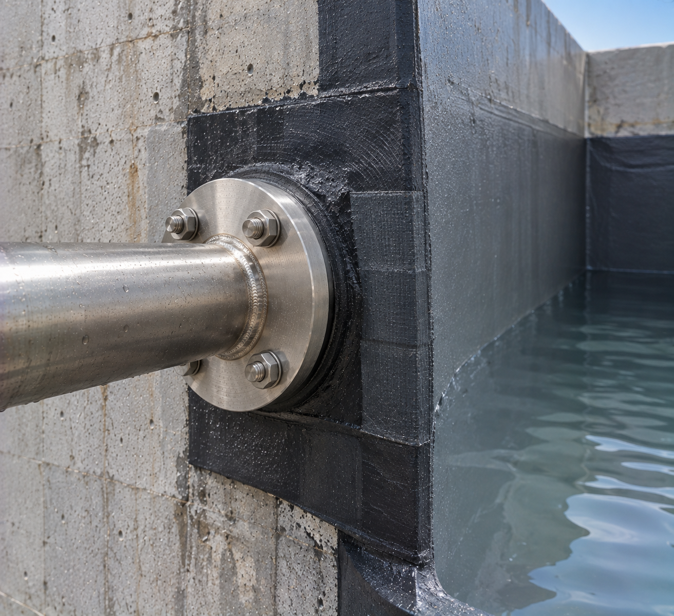
The plate interrupts water tracking along the outside of the pipe within the concrete section.
Puddle Flange Waterproofing helps control water migration where pipes cross concrete walls, slabs and tanks. First, define the water exposure and pipe; then, coordinate the plate, concrete, membranes, joints and inspection.
Puddle Flange Waterproofing addresses the path where a pipe or sleeve passes through concrete. Because smooth pipe surfaces can create a direct interface through the structure, water may track along the outside of the penetration.
A projecting puddle plate interrupts that route and increases the path through the concrete. Consequently, it supports watertight details in walls, slabs, tanks, sumps and treatment structures.
However, the puddle flange does not replace construction-joint waterbars, external membranes, internal linings, pipe-joint seals or structural crack control. Instead, the designer must coordinate every waterproofing component as one system.
A reliable detail starts with the expected water exposure and the actual penetration geometry. Therefore, project drawings should define the following information.
| Structure | Concrete wall, slab, tank, basement, pit, sump or another water-retaining or below-grade element. |
|---|---|
| Water exposure | Stored water, groundwater, hydrostatic head, intermittent wetting or process-liquid exposure. |
| Pipe data | Material, nominal size, actual OD, wall thickness or SDR and expected movement. |
| Puddle plate geometry | Outside diameter or width, radial projection, thickness, profile and pipe attachment. |
| Embedment position | Drawing-defined location within the concrete and required cover on both plate faces. |
| Concrete clearance | Space around reinforcement and embedded items for placement and consolidation. |
| Material compatibility | Pipe, plate, welding, bonding, gasket, coating and surrounding waterproofing materials. |
| Adjacent waterproofing | External membrane, internal lining, waterbar, joint sealant and termination details where applicable. |
| Inspection stages | Factory checks, pre-pour inspection, concrete review and specified water or pressure testing. |
| Repair access | Accessibility of exposed pipe joints, coatings and seals after construction. |
Design note: No universal plate size guarantees waterproofing. Instead, the responsible designer should establish the geometry from the structure, pipe, water head, reinforcement and project requirements.
Each system component controls a different route or junction. Consequently, the project should avoid treating them as interchangeable.
The plate interrupts water tracking along the outside of the pipe within the concrete section.
An external membrane protects the concrete surface. Moreover, its penetration termination needs an approved detail.
A waterbar controls leakage at a concrete joint rather than at the pipe surface. Therefore, coordinate it separately.
Gaskets, flanges, couplings or welded joints control leakage through the connected pipeline itself.
Review related guidance for concrete wall penetrations, slab penetrations and coordinated sealing systems.
New concrete and existing structures require different penetration strategies. Therefore, identify the construction condition before selecting the product.
For new work, a fixed puddle plate can arrive attached to the pipe at the drawing-defined location.
Alternatively, an adjustable puddle flange may provide approved positioning flexibility before concrete placement.
For existing pipes, a loose or split puddle flange may suit restricted-end-access conditions.
A retrofit penetration may require an engineered annular seal, grout, membrane termination and movement detail in addition to any water stop.
Retrofit note: Do not assume that a cast-in puddle flange detail can be reproduced after the concrete has cured. Instead, use a retrofit system designed and approved for the existing opening.
Correct installation protects the designed water-stop path and reduces the risk of voids beside the plate.
First, confirm pipe size, plate geometry, embedment, water side, joints and membrane interfaces.
Next, check the pipe, plate, attachment, coating, cleanliness and protective covers.
Then, maintain the specified clearances from bars, waterbars, joints and other embedded items.
Use rigid independent supports to hold line, level and plate position during the concrete pour.
Afterwards, fill both plate faces and the complete circumference without moving the pipe.
Finally, complete the specified curing, waterproofing interfaces and water or pressure tests.
Most failures relate to incomplete design coordination, poor installation or damage rather than the product name alone. Accordingly, inspect these conditions.
First, inadequate clearance or consolidation can leave voids beside the plate and weaken the intended barrier.
Next, a misplaced or tilted plate can conflict with cover, reinforcement and membrane terminations.
Moreover, construction handling can damage joints and exposed protective finishes.
Finally, settlement, thermal movement or external pipe loads can stress the penetration and connected seals.
For broader building-envelope context, project teams can consult the WBDG waterproofing guidance. However, the approved local design and project specification must govern the work.
Projects use embedded water stops wherever a pipe crosses a concrete boundary exposed to water. For example, applications include:
Additionally, review water-tank penetrations, fire-water tank puddle flanges and drain applications.
To review the product and waterproofing interface, send these details:
Its projecting plate interrupts the direct path along the pipe-to-concrete interface. Consequently, water must follow a longer route through the concrete.
No. A membrane protects a surface or junction, while the puddle plate addresses the embedded pipe interface. Therefore, many projects need both.
Yes, when the approved design coordinates plate dimensions, concrete cover, reinforcement, pipe support and water exposure.
A conventional cast-in product cannot simply be added inside cured concrete. Instead, existing penetrations require an approved retrofit sealing detail.
Possible causes include concrete voids, cracks, damaged attachments, incompatible materials, pipe movement or leakage from the connected pipe joint.
The designer should determine its projection and thickness from the pipe, structure, water head, reinforcement and project requirements.
First, send the pipe and concrete data. Then, include the plate geometry, installation condition, waterproofing interfaces, tests, quantity and drawing.
Send Mesta Inc. your pipe dimensions, puddle plate details, material, drawing, quantity, inspection scope and delivery requirements. Then, our team will review the enquiry and confirm the appropriate manufacturing scope.