
Fire Pump Suction Puddle Flange
A tank suction penetration connects the stored reserve to the fire pump system. The hydraulic design should control its size and position.
Mesta Inc. manufactures a Puddle Flange for Fire Water Tank penetrations according to approved tank and piping drawings. Moreover, we coordinate the pipe size, water-stop plate, wall or base embedment, connection ends, material, coating and inspection scope.
A Puddle Flange for Fire Water Tank construction forms a fixed water stop around a pipe that crosses the concrete wall or base. The projecting plate becomes embedded in concrete and interrupts water tracking along the pipe surface. Therefore, it helps protect suction, fill, overflow, drain and test-line penetrations.
The puddle flange controls the pipe-to-concrete seepage path. However, it does not replace the pipe joint, flange gasket, wall waterproofing, construction-joint waterbar or structural crack-control system.
Mesta Inc. manufactures each pipe puddle flange from a reviewed drawing. Buyers define the actual pipe OD, plate geometry, tank thickness, projection lengths and connection details.
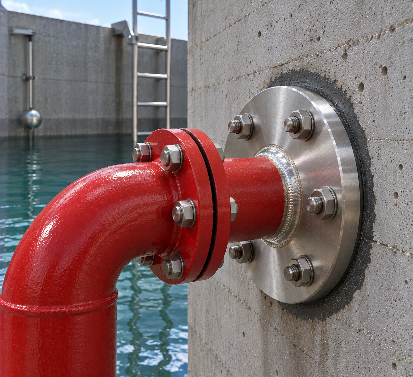
Tank duty alone cannot define the finished component. Accordingly, every enquiry should include the dimensional and service requirements.
| Line function | Suction, inlet, make-up, overflow, drain, test return or another drawing-defined duty. |
|---|---|
| Pipe size | Nominal bore plus actual outside diameter, wall thickness or schedule. |
| Material | Carbon steel, stainless steel or another project-approved pipe and plate grade. |
| Puddle plate | Outside diameter or width, thickness, profile, radial projection and location. |
| Tank penetration | Wall or base thickness, elevation, orientation and required concrete cover. |
| Connection ends | Plain, bevelled, spigot or flanged ends with complete mating-interface data. |
| Flange details | Standard, size, class or PN rating, facing, drilling and bolt-hole orientation. |
| Protection | Specified internal and external coating, galvanizing or stainless surface treatment. |
| Inspection | Material traceability, dimensions, weld checks, coating and agreed pressure testing. |
Hydraulic note: The fire-protection designer should size every tank connection from the required flow, available head, pump arrangement and governing project criteria.
Each line performs a different function. Consequently, its elevation, diameter, projection and external joint may differ.
A tank suction penetration connects the stored reserve to the fire pump system. The hydraulic design should control its size and position.
The fill or make-up line enters through the wall or roof zone shown on the coordinated tank drawing.
An overflow penetration carries excess water safely away. Designers should coordinate its invert and discharge route.
A low-level drain supports tank emptying and cleaning. Therefore, the detail should allow isolation and maintenance access.
For bolted interfaces, review our puddle flange connection and double flanged pipe pages.
First, confirm the line duty and tank geometry. Next, coordinate the assembly with the structural, mechanical and waterproofing drawings.
Project teams may consult the National Fire Protection Association for fire-protection codes and standards. Nevertheless, the locally adopted code and approved project documents must govern the installation.
Compliance note: A puddle flange is one penetration component. The fire-water tank, pumps, valves, controls and pipework require a complete system design by the responsible fire-protection professionals.
Accurate setting keeps the pipe aligned with the tank and downstream fire-water system.
First, confirm the line tag, grid position, elevation, orientation and drawing revision.
Next, check the pipe, plate, ends, welds, coating, identification and protective covers.
Confirm clearance from bars, waterbars, joints and other embedded components.
Use independent supports to maintain position, alignment and plate embedment during concreting.
Then, compact concrete around the full plate without moving the pipe or damaging its finish.
Finally, complete the external joints and perform the specified tank and pipeline tests.
Inspection should cover fabrication, installation and the completed tank penetration. Typical checks include:
Inspectors verify certificates, pipe OD, wall thickness, plate geometry and assembly length.
The team examines specified welds, surface preparation, coating thickness and handling damage.
Site checks confirm the line tag, elevation, orientation, embedment and reinforcement clearance.
After installation, the project team completes the required tank tightness and pipework tests.
These assemblies support concrete fire-water storage and associated pump facilities. Common uses include:
Depending on the project, buyers may also compare a CS water tank puddle flange or stainless steel puddle flange.
Send complete tank and piping data so the quotation matches the fire-water design.
It is a pipe assembly with an external plate embedded in the tank wall or base. The plate helps interrupt water tracking beside the penetration.
Suction, inlet, overflow, drain, return and test lines may need them when they pass through concrete. The approved tank design identifies the required locations.
Yes. Specify the flange standard, size, rating, facing, drilling and bolt-hole orientation for each end.
No. The puddle plate controls seepage beside the embedded pipe, while the gasket seals the bolted pipe joint.
Options may include coated carbon steel, stainless steel or another approved material that suits the fire-water system and tank environment.
Yes, when the structural and fire-protection design permits a base penetration and defines its embedment, support and waterproofing details.
Provide the line duty, pipe and plate dimensions, tank thickness, connections, material, coating, testing, quantity and drawings.
Send Mesta Inc. your tank drawing, line duties, pipe dimensions, puddle plate details, connections, quantity and inspection requirements. Then, our team will review the enquiry and confirm the appropriate manufacturing scope.