
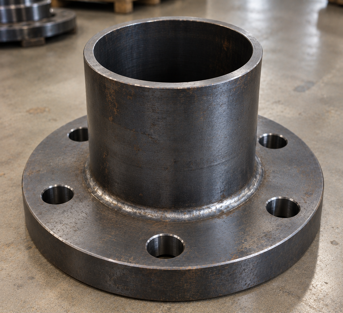
Plain-End Tank Sleeve
Plain projections allow the approved site connection method. Moreover, the drawing must define the accessible length on each tank face.
Mesta Inc. manufactures CS water tank puddle flange assemblies for tank inlets, outlets, drains and overflow connections. Moreover, we follow the approved pipe, puddle plate, sleeve, flange, coating and inspection requirements.
A pipe passing through an RCC water-tank wall creates an interface where stored water can track along the outside surface. Consequently, the penetration needs a drawing-defined water stop and suitable pipe connections.
A CS water tank puddle flange combines a carbon-steel pipe or sleeve with a projecting puddle plate. The plate remains embedded in the concrete and interrupts the direct seepage path. Therefore, it supports watertight inlet, outlet, drain and overflow penetrations.
Mesta Inc. manufactures each assembly to the approved tank drawing. Buyers can specify pipe size, wall thickness, puddle plate dimensions, sleeve length, end flanges, welding, coating and documentation. For broader configurations, review our puddle flange pipe assemblies.
A complete tank penetration specification must identify the carbon-steel grade, geometry and protection system. Therefore, send the approved drawing or provide every item below.
| Pipe size | Project-defined nominal size plus outside diameter and wall thickness or schedule. |
|---|---|
| Pipe material | Specified carbon-steel pipe standard and grade; “CS” alone does not define the material. |
| Puddle plate material | Separately specified carbon-steel plate standard, grade and thickness. |
| Plate geometry | Outside diameter or width, radial projection, thickness, opening and permitted tolerances. |
| Sleeve length | Tank-wall thickness plus the required internal and external pipe projections. |
| Plate position | Drawing-defined location within the RCC wall and coordinated with reinforcement. |
| End connections | Plain, bevelled, threaded, socket, single-flanged or double-flanged as specified. |
| Flanged ends | Separate flange material, standard, class or pressure designation, facing, drilling and orientation. |
| Coating | Project-approved internal and external coating system, surface preparation and inspection criteria. |
| Quality documents | Material certificates, weld/NDT records, dimensions, coating reports and release documents as agreed. |
Material note: “CS” means carbon steel, but it does not identify one grade. Therefore, specify separate standards and grades for the pipe, puddle plate, fittings and end flanges.
The tank nozzle schedule and connected piping determine the required end arrangement. Consequently, each configuration needs distinct dimensions and connection data.
Plain projections allow the approved site connection method. Moreover, the drawing must define the accessible length on each tank face.
One bolted flange connects equipment or external piping on the specified side of the tank wall.
Flanges on both ends create bolted internal and external connections. However, both flange orientations require dimensional control.
A flanged end and a plain or spigot end can support different connection methods on opposite sides.
Review related single-flanged pipes, double-flanged pipes and flange-spigot puddle pipes.
Carbon steel offers strong fabrication flexibility, but water exposure requires a suitable material and coating strategy. Therefore, the project team should consider:
Potable-water note: Use only a coating system that the project approves for the intended water service. Moreover, obtain the required compliance documents before installation.
A controlled sequence links tank geometry, fabrication records and final penetration position.
First, confirm penetration number, elevation, orientation, wall thickness and connected piping.
Next, match pipe, plate, fitting and flange markings with the approved bill of materials.
Then, cut the sleeve, position the puddle plate, fit connection ends and complete welding.
Inspectors verify dimensions and welds before the specified surface preparation and coating work.
At site, installers support the assembly at the correct elevation, line and flange orientation.
Finally, workers consolidate concrete around the full puddle plate without disturbing the penetration.
The approved inspection plan should cover materials, welds, geometry and coating. Accordingly, typical control points include:
First, certificates and markings connect the carbon-steel pipe, plate and flanges to the BOM.
Inspectors perform visual and specified NDT according to the approved acceptance criteria.
They verify sleeve length, plate position, flange face alignment, drilling orientation and elevations.
Finally, the team checks surface preparation, dry-film thickness, holidays or other specified criteria.
Tank drawings may use carbon-steel penetration assemblies for several hydraulic and utility functions. For example, common locations include:
Additionally, buyers can review puddle flanges for water tanks, fire-water tank penetrations and concrete-wall puddle flanges.
For accurate fabrication and pricing, send the tank penetration schedule and these details:
It is a carbon-steel pipe or sleeve assembly with a projecting water-stop plate for an RCC tank wall. The plate helps interrupt water tracking along the pipe-to-concrete interface.
CS means carbon steel. However, it does not identify a specific material standard or grade. Therefore, specify each component material separately.
Yes. A double-flanged assembly supports bolted connections on both tank faces. Buyers must define both flange standards, facings and orientations.
The project should select a coating according to water type, exposure, design life and regulatory requirements. In addition, potable-water service may require specific approvals.
Provide the plate OD or projection, thickness and position along the sleeve. Also include the tank-wall thickness and reinforcement clearances.
They use suitable independent supports to maintain elevation, line, end projection and flange orientation during formwork and concreting.
First, send the tank drawing and penetration schedule. Then, provide all pipe, plate, flange, welding, coating, inspection and delivery requirements.
Send Mesta Inc. your pipe dimensions, puddle plate details, material, drawing, quantity, inspection scope and delivery requirements. Then, our team will review the enquiry and confirm the appropriate manufacturing scope.