
Plain-End UNS N08825 Puddle Pipe Flange
Plain or bevelled ends allow the contractor to complete a compatible welded, coupled or site-defined connection.
A UNS N08825 puddle pipe flange combines an Alloy 825 pipe spool with an integral water-stop plate for installation through concrete. Mesta Inc. manufactures each assembly to the approved drawing; therefore, buyers can specify its material standard, pipe size, overall length, plate position and connection ends.
A UNS N08825 puddle pipe flange combines a fabricated Alloy 825 spool and a projecting plate in one installation-ready unit. When workers embed the plate in a wall, slab or tank, it lengthens the potential moisture path around the pipe exterior.
UNS N08825 identifies a nickel-iron-chromium alloy containing additions such as molybdenum, copper and titanium. Because suitability depends on the actual chemical environment, temperature and contaminants, the purchaser should confirm material selection through the project corrosion assessment.
Mesta Inc. manufactures every unit from an approved drawing or complete dimensional enquiry. Consequently, the finished product can match the required material specification, plate location, connection orientation, fabrication controls and inspection plan.
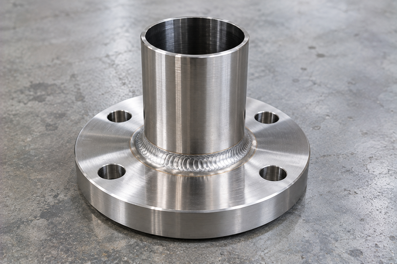
A nominal pipe size does not define the complete product. Therefore, every quotation should confirm the pipe system, water-stop geometry and connection details.
| Pipe size | Project-defined nominal size plus confirmed actual outside diameter. |
|---|---|
| Pipe wall | Schedule, SDR, pressure class or actual wall thickness according to the pipe material. |
| Water-stop plate | Outside diameter or width, radial projection, thickness, profile and pipe opening. |
| Plate position | Drawing-defined location along the pipe and within the concrete wall, slab or tank. |
| Material | UNS N08825 pipe, plate, flange and fitting product forms according to the approved material specification. |
| Assembly length | Length based on concrete thickness, internal projection, external projection and joint access. |
| End connections | Plain, bevelled, threaded, socket, spigot, single-flanged or double-flanged. |
| Surface condition | Project-defined cleaning, contamination control and finished surface requirements. |
| Inspection | Material, dimensions, attachment, welds, coating and testing according to the approved plan. |
| Documentation | Material certificates, weld/NDT reports, dimensional records and release documents as agreed. |
Size note: Nominal metric and inch descriptions may use different physical outside diameters. Therefore, provide the pipe standard or measured OD with the enquiry.
The adjoining pipework and site assembly method determine the correct end arrangement. Consequently, compare these common configurations.
Plain or bevelled ends allow the contractor to complete a compatible welded, coupled or site-defined connection.
A single-flanged assembly combines one bolted connection with a plain, bevelled, socket or spigot end.
A double-flanged assembly provides bolted connections on both sides of the concrete penetration.
A flange-and-spigot configuration supports systems that require different connections at each end.
For a broader comparison, review our design and material guide.
The correct specification depends on the process medium, impurities, temperature, joining method and required service life. Therefore, review these factors before approving production:
UNS N08825 identifies a nickel-iron-chromium alloy; material certificates should confirm the chemistry, properties and ordered product specification.
Alloy 825 performs differently across acids, chlorides and other media. Accordingly, the project materials engineer should assess the complete chemistry and temperature.
Pipe, plate, flanges, fittings and filler metal should follow the approved bill of materials and fabrication specification.
Dedicated handling, suitable tools and project-defined cleaning help limit surface contamination during cutting, forming and welding.
Selection note: The UNS number alone does not complete the design. Also confirm the material standard, product form, dimensions, fabrication procedure, service conditions and acceptance criteria.
A controlled sequence connects approved dimensions with material identity, fabrication and site position.
First, confirm pipe data, plate dimensions, assembly length, ends and inspection requirements.
Next, match pipe, plate, fitting and flange materials with the approved bill of materials.
Then, cut the pipe and plate and prepare all required openings, edges and connection ends.
Fabricators set the water-stop position and complete the approved welded, bonded or mechanical attachment.
Afterwards, inspectors check dimensions, joints, ends, surface treatment and identification.
Finally, installers support the assembly while workers consolidate concrete around the complete plate.
Inspection should address the manufactured product and its final position before concrete placement. Accordingly, typical checks include:
First, markings and certificates connect each component with the approved specification.
Next, inspectors verify pipe OD, length, plate geometry, position and connection orientation.
Moreover, the team checks the specified weld, bond, clamp or mechanical joint.
Finally, site personnel verify line, level, support, reinforcement clearance and concrete access.
Projects may specify Alloy 825 assemblies where a concrete penetration also faces a demanding chemical or marine environment. Subject to the project corrosion assessment, applications can include:
For the water-stop design context, review our pipe-penetration waterproofing guide. In addition, the independent WBDG below-grade systems guide explains broader moisture-control considerations for concrete structures.
Send a drawing or provide the following information for an accurate technical and commercial review:
It is a fabricated Alloy 825 pipe section with an integral projecting water-stop plate for installation through concrete.
Projects use it in tanks, walls, slabs, basements, pits, treatment structures and other concrete pipe penetrations.
Yes. The assembly may include plain, bevelled, threaded, socket, spigot or flanged ends according to the specified piping system.
UNS N08825 is the Unified Numbering System designation commonly associated with Alloy 825. The purchase order should still state the complete product specification.
Confirm the actual pipe OD, wall, plate dimensions, concrete thickness and assembly length instead of relying only on nominal size.
No. It controls the embedded pipe interface, while membranes, waterbars, linings and pipe-joint seals address other leakage paths.
First, send the drawing or pipe data. Then, include the plate geometry, material, connections, finish, inspection, quantity and delivery requirements.
Send Mesta Inc. your pipe dimensions, puddle plate details, material, drawing, quantity, inspection scope and delivery requirements. Then, our team will review the enquiry and confirm the appropriate manufacturing scope.